Project diary - Paul Chao's Pittsburgh Topographic Map
It’s been a little over six years since I’ve updated this blog. Since then, I’ve graduated from college, started and finished a Masters program, and started a full-time job.
My job has a makerspace, and I’ve been learning to 3D print and use the laser cutter. I’ve wanted to make a 3D topographic map for a while, and it just so happens that Paul Chao had already done the hard work of getting the contour data and was kind enough to post his DXF files and Rhino .3dm files for anyone to use.
Here are my Adobe Illustrator files.
Opening the files
At first, the makerspace recommended using Microsoft Visio to open and send files to the Universal laser cutter. Microsoft Visio is a flowchart and diagramming software with a very impoverished web version and no easy way to install the software locally. While it was technically capable of opening .dxf files, it was very difficult to scale them and nigh-impossible to manipulate the vector contours.
Because of the difficulty of using Microsoft Visio, I gave up on the project for a few months, until the makerspace discovered that a copy Adobe Illustrator was installed on the computer connected to the laser cutter. I had some experience using Adobe Illustrator from a graphic design class in high school, so this was a fantastic development that enabled me to actually do this project instead of thinking about it.
I set the canvas size in Illustrator to 24” x 18”, the size of the laser cutter bed, and imported the .dxf files. I scaled the files by 50%, because that was a nice round number to work with as I was doing test cuts and experimenting with the files. I was planning to increase the size of the final product, probably to around a 60% or 70% scale instead so the city would stretch from end to end of the 24” x 18” laser cutter bed, but I forgot. My final map is around 18 inches wide.
Paul’s files were separated roughly into vector cut and raster engrave layers set up for the laser cutter he was using. For my makerspace’s laser cutter, I had to change the vectors to be cut into pure red (#FF0000) and to be 0.001 pt wide. The raster engrave layers could be any color, so I changed them into pure black (#000000) and left them as is, after scaling.
I made a few changes to the files. Layer 0 had the rivers cut out, so I removed those vectors so Layer 0 is just a solid cutout of the outline of the city limits. Layer 2 also only had part of the city, so I had to use a trial version of Rhino3D to open the .3dm file Paul provided and extract the contours, import them into Illustrator, manually line them up with the existing Layer 2, and look back and forth between Layer 3 and Layer 2 to see which contours were actually part of Layer 2. I made some small additions to the later layers of the Westwood/Oakwood/East Carnegie penninsula, and I also added a small Layer 7 with some tiny pieces and inconsistencies with Paul’s Layer 6 that didn’t make sense to me. I stared hard at the City of Pittsburgh’s interactive topographic map to see if Paul got the contours around the edges right. I think there is a little hook-like piece at the south border of the city that I think should be elevation instead of depression – it can be hard to tell whether the area between the border and the first contour line is a depression or an elevation, i.e. does it slope down or up.
For the later layers, which have a lot of small pieces, I found it really helpful during assembly to add an additional layer to the files with the outline of the city, and roughly place each little piece where it would go on the map. Then, I separated the cut and engrave layers into smaller batches of 3-5 pieces each. Because the Universal Laser Systems (ULS) software was smart enough to only cut the areas that were marked with black or red lines, and not the whole canvas, I was able to position each batch separately on the wood and save some wood that way.
One interesting thing to note is that there is a gap in the City of Pittsburgh, a little south of the South Side Flats, between Knoxville on the west and Mt. Oliver on the east. There’s no road data here, so it showed up as a blank spot on the map, but it didn’t like the contours were affected, at least not in a major way. Luckily, it’s small enough that it’s not noticable unless you’re looking for it.
Wood materials
I used 3.30mm plywood for this, and for each map, I went through around 3-5 sheets of 24” x 18” plywood, even trying to be efficient with the placement of the smaller pieces. I liked the wood texture of the plywood more than the medium density fiberboard that the makerspace had.
Painting the rivers
The first thing I did was cut out the base layer (Layer 0) and the layer after that (Layer 1) and position them on top of each other. I used a pencil to trace an outline around Layer 1 onto Layer 0, and when I went to paint, I made sure I painted over the pencil markings and then some.
Paul used a really vibrant blue to paint the rivers. I had a tough time finding such a vibrant blue in the student-grade acrylic paints that my makerspace had, and it’s really hard (impossible? without a deep understanding of color theory and even then using some trickery) to mix paints to get a paint that is more saturated than the paints you started with. I ended up using a miniatures paint, which was certainly newer and less chunky and dried than the old student-grade acrylics in the makerspace, and also had a higher pigment density. I believe I used Army Painters Crystal Blue – it might have been Voidshield Blue, but I think that one was too light for the water. I know the river water is not at all that color, but I really liked how that high-saturation high-luminosity medium tone blue stood out with the yellow-brown of the wood and laser cut edges.
Since the miniatures paint was pretty thick with pigment, I only needed one thick layer, with a little more paint to touch up some spots afterwards. I did a quick and dirty job, focusing on getting solid color coverage without leaving pools of paint, and the paint interacted well with the wood.
Cutting & pasting
Laser cutting and raster engraving in particular TAKES A LONG TIME. I spent 20 hours or so on the first map, and I was running the laser cutter for 12-16 of those hours.
Laser cutting vectors (and etching vectors - some people call this “scoring” instead of “engraving”) is reasonably fast, but it still took 10-20 minutes for the laser to just cut out the outline of the city of Pittsburgh.
When cutting and raster engraving Layer 1, it took 50 minutes to a little over an hour. It takes a long time to raster engrave because the laser head has to move all the way across the width of the cut area, no matter how much there actually is to engrave. But, you can change the size and thickness of the lines when raster engraving, so it scales better than scoring / except at very small scales, where the design can become patchy.
I used the “General Medium Woods” setting on the laser cutter, with the red cut and black raster engrave powers cranked up all the way to +50%.
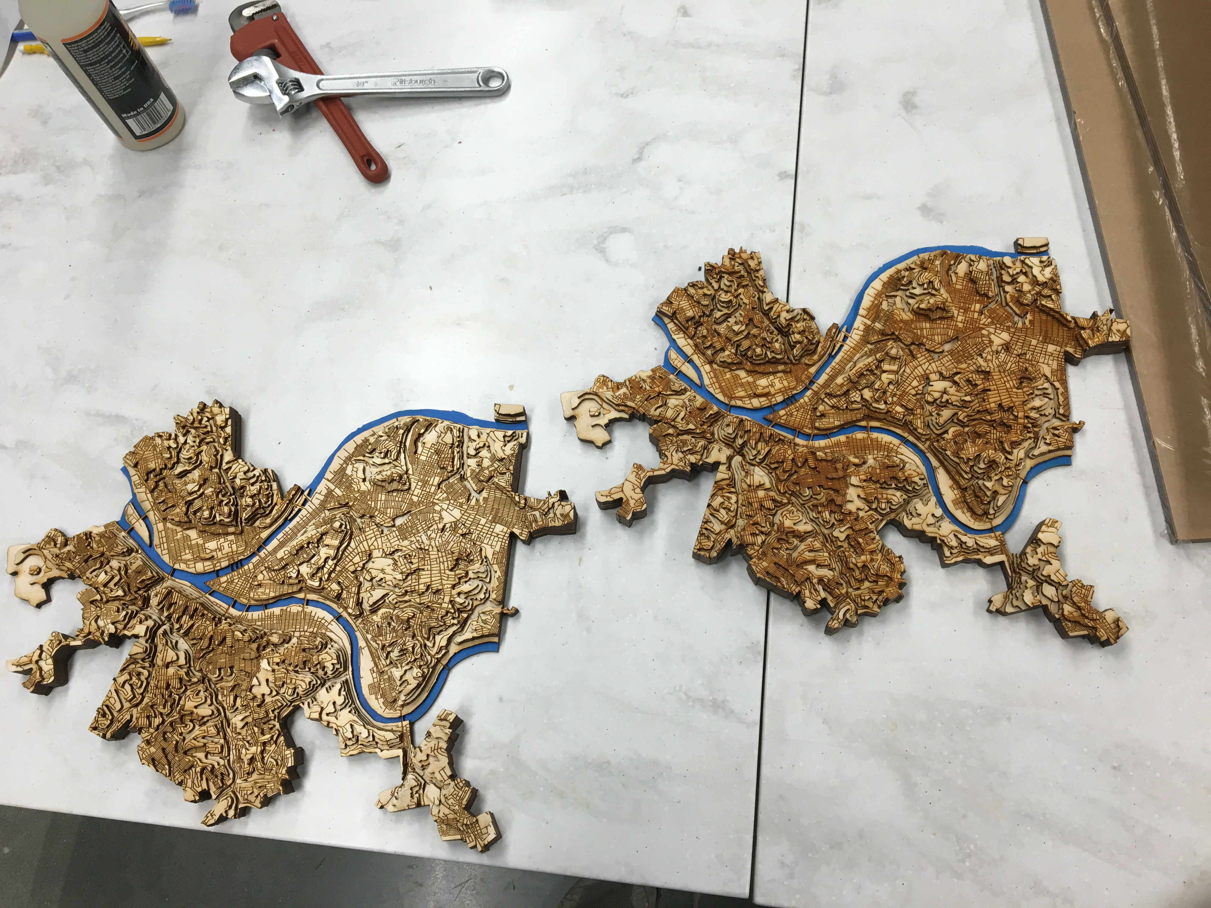
Even smaller batches of 3-5 pieces took 10-15 minutes to cut out. And there are a lot of pieces, especially in the later layers. Luckily, I had a lot of gluing to do in between waiting for the laser to finish, and I had laser cutting to do while waiting for the glue to dry.

I used Gorilla Glue wood glue with the aid of some clamps to glue the pieces together. I tried a few different ways of spreading this glue, including using a toothbrush and a small paint spreader. Both were ok. I liked how the spreader could move a lot more glue, but the toothbrush did a better job of making the glue “soak into” the wood.
I found this glue to have a very strong cohesion, to the point where I’d spread it onto the wood, go to spread some other part of a larger piece, and it would “shrink back” and pull itself into blobs instead of evenly coating the wood. This was an advantage for the edges, because I’d often spread a little bit of glue over the edges and it would “pull back” like honey out of a spout, but that didn’t always happen. It also advertises a working time of up to 15 minutes, but I found I had to hustle on the bigger pieces, because the glue seemed less visible and certainly effective after 5 minutes or so of sitting out in the open.
When applying the wood glue, I was careful not to leave drops of it on the edges of the piece. I used either a finger or a paper clip to “grab” the excess glue drops off the irregular edges as I was applying it. The glue says you can sand it after it dries, but it would have been awkward with the geometry of the laser cut edges, and I wanted them to have a nice uniform burnt edge. When the glue dries in a drop, it dries a dark, barely translucent brown. If a little bit of glue was squeezed out between two layers and dried, I was able to use a paper clip to scratch off the excess, which would sometimes leave a little bright mark where the glue broke off.
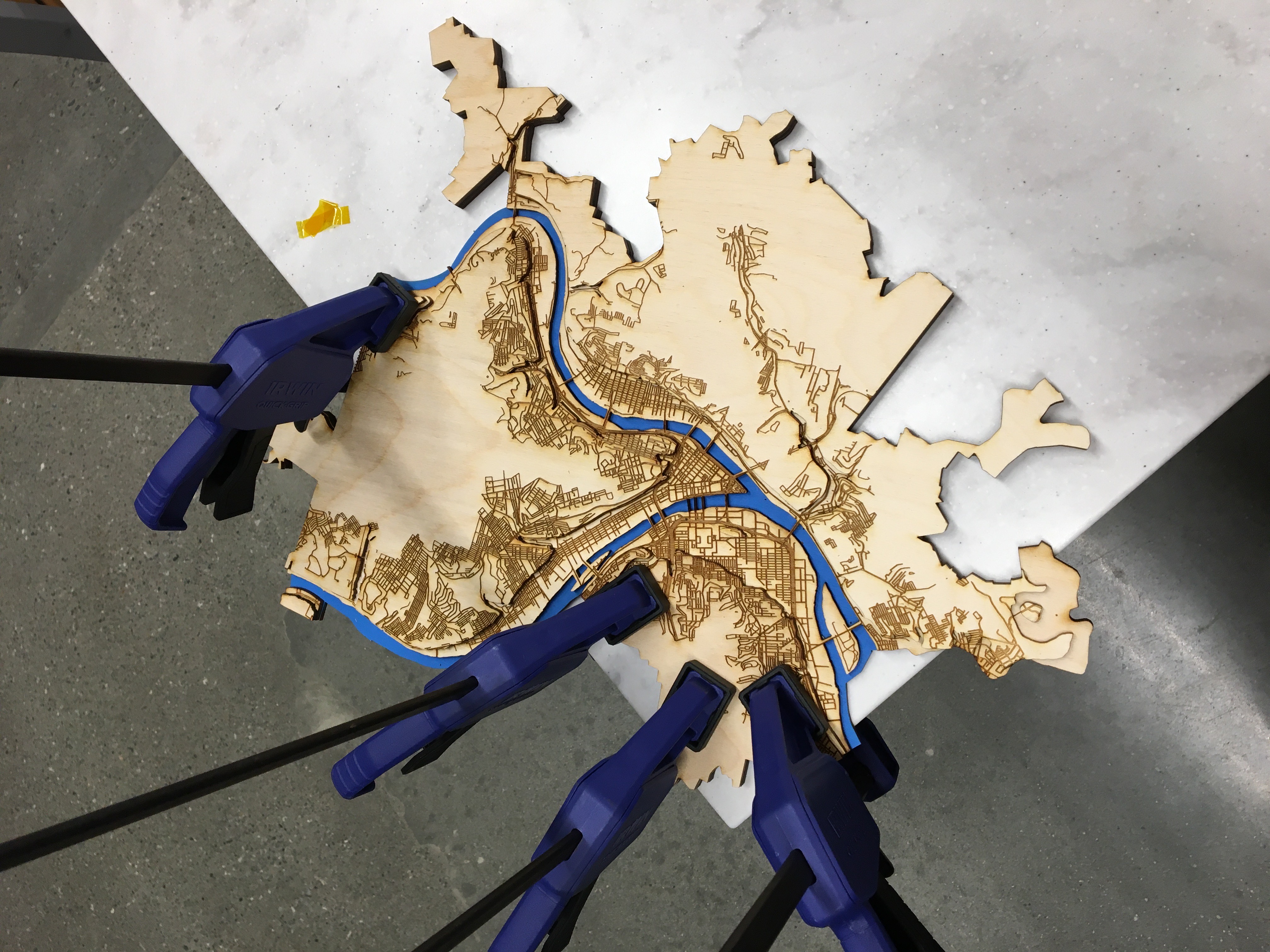
The key part of working with wood glue is to clamp your pieces together at as many edges as you can. Even if you only get a little bit on, the glue will melt the wood and re-form a very strong bond if you can press the pieces together. Since I was working on a large table, I set the map on a corner of the table, and I could only clamp two sides at a time and maybe the center of the piece, if it was small enough and I maneuvered it onto the corner of the table. I tried to use heavy things like crescent wrenches and monkey wrenches to weigh down the edges that I couldn’t clamp, and I’m sure it was better than nothing, but it also wasn’t very effective. Sometimes, if one edge wasn’t properly clamped, it would stick up, and I would put some glue on the scraper, work it under that edge, then clamp that edge and wait for it to dry again.
The wood glue told me to let it dry while clamped for 20-30 minutes. While I was waiting for the wood to dry, I was laser cutting other pieces and labeling them with their layer number and batch number so I wouldn’t lose track of them. I usually found that 20 minutes was sufficient, and even possibly as few as 15 or even 10 minutes while clamped.
For the smaller pieces in the later layers, I often found it was sufficient to just press down hard for 5-10 seconds and leave it, especially for the pieces smaller than a fingernail. Clamping small pieces is tough, because the force of the clamp can often cause the piece to shift a little bit, misaligning the roads in an annoying way.
Cutting and gluing the wood was the vast majority of the project time. Probably 12-16 hours of the 20 hours was spent doing at least one of the two, and often both at the same time. I started making my second version of the topographic map while I was waiting for the glue to dry on some of the last layers of the first one.
Spraying & sealing
Since I had some U.S. Art Supply matte airbrush sealer from my Star Wars blaster rifle, I decided to seal the first topographic map using it. However, I had the same problems spraying it out of the single-action airbrush as I had in the other project. U.S. Art Supply matte airbrush sealer is really gunky, so within a minute or two of spraying, it would either clog up the airbrush nozzle, the intake straw and well, or even the little air hole at the top of the little paint bottle. De-clogging it was also a pain. I used the U.S. Art Supply airbrush cleaner, then isopropyl alcohol (yes I was wearing a respirator, yes I know breathing IPA is bad) with the aid of a paper clip to clean out the clogs, since it seemed like there was a good amount of gunk that required physical force to remove.
Other than the clogging problem, the U.S. Art Supply matte airbrush sealer worked ok. Since it’s a matte sealer, it dries into a bumpy surface rather than a smooth surface. You’re not supposed to let it pool, but if you do, then it starts to provide a little more of an even, glossy look, and it didn’t have too much of a white cast. Even though the Amazon product page says that it’s good to use on wood, I’m not sure if it’s really the best choice.

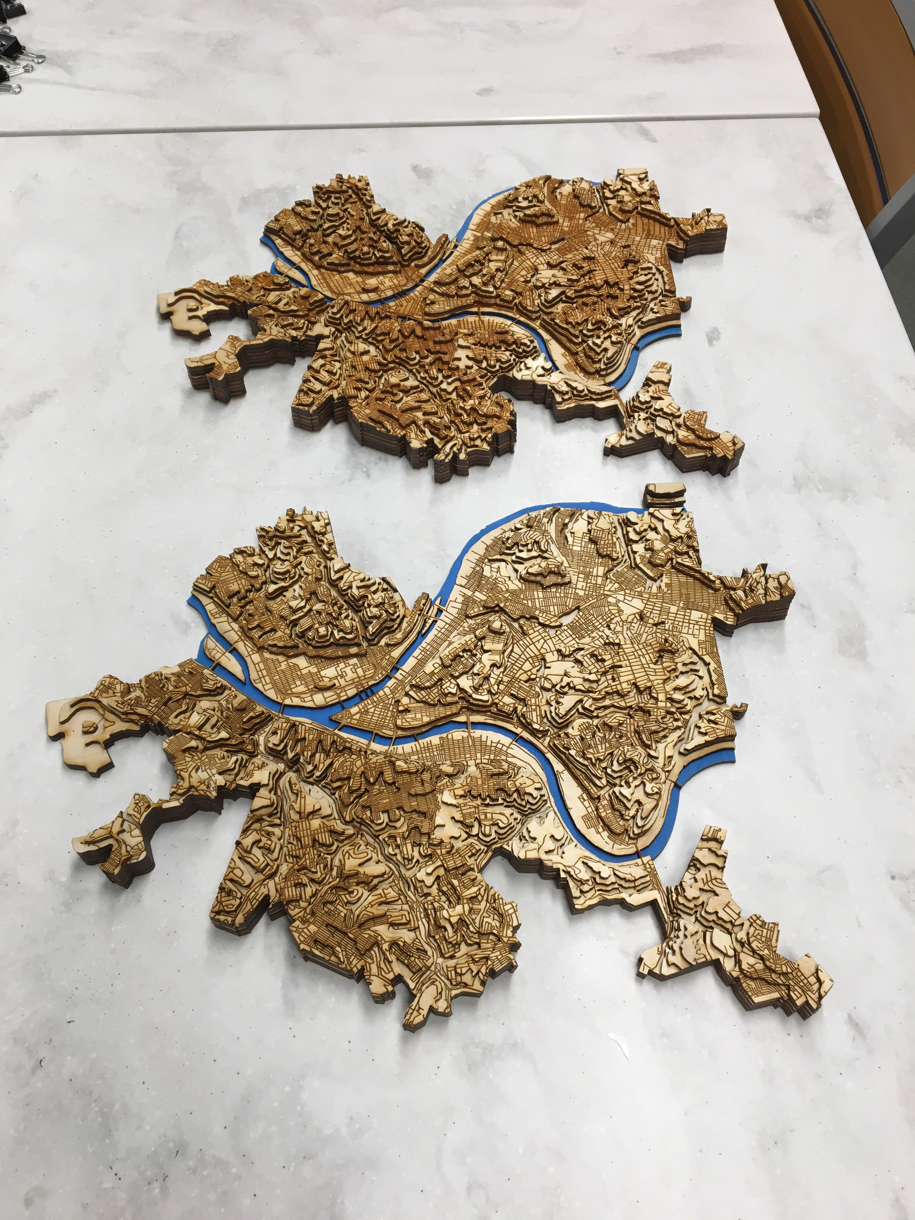
Left is unsealed, right is sealed.
For the second topographic map, I bought spray-on Shellac. It worked well – in truth, about the same as U.S. Art Supply matte airbrush sealer, but the Shellac rattle can had no clogging problems. There’s less Shellac in the spray can than you think. Both sealers darkened the wood and gave it a nice burnt look.

When spraying, I started with even coverage. In the later layers, I paid special attention to the valleys, which didn’t get as much spray as the peaks or the rivers (where the runoff would collect). I’m not sure if I got a solid layer of sealer on the valleys before the peaks built up a solid glaze of sealer and I had to stop before they got too “candied”.
Mounting
I didn’t have any good ideas on how to mount it, except by using the white “velcro” Command strips used for picture hanging. Two or three of the “large” ones did the trick. The map is about as heavy as you’d expect, or maybe a little lighter.
Takeaways

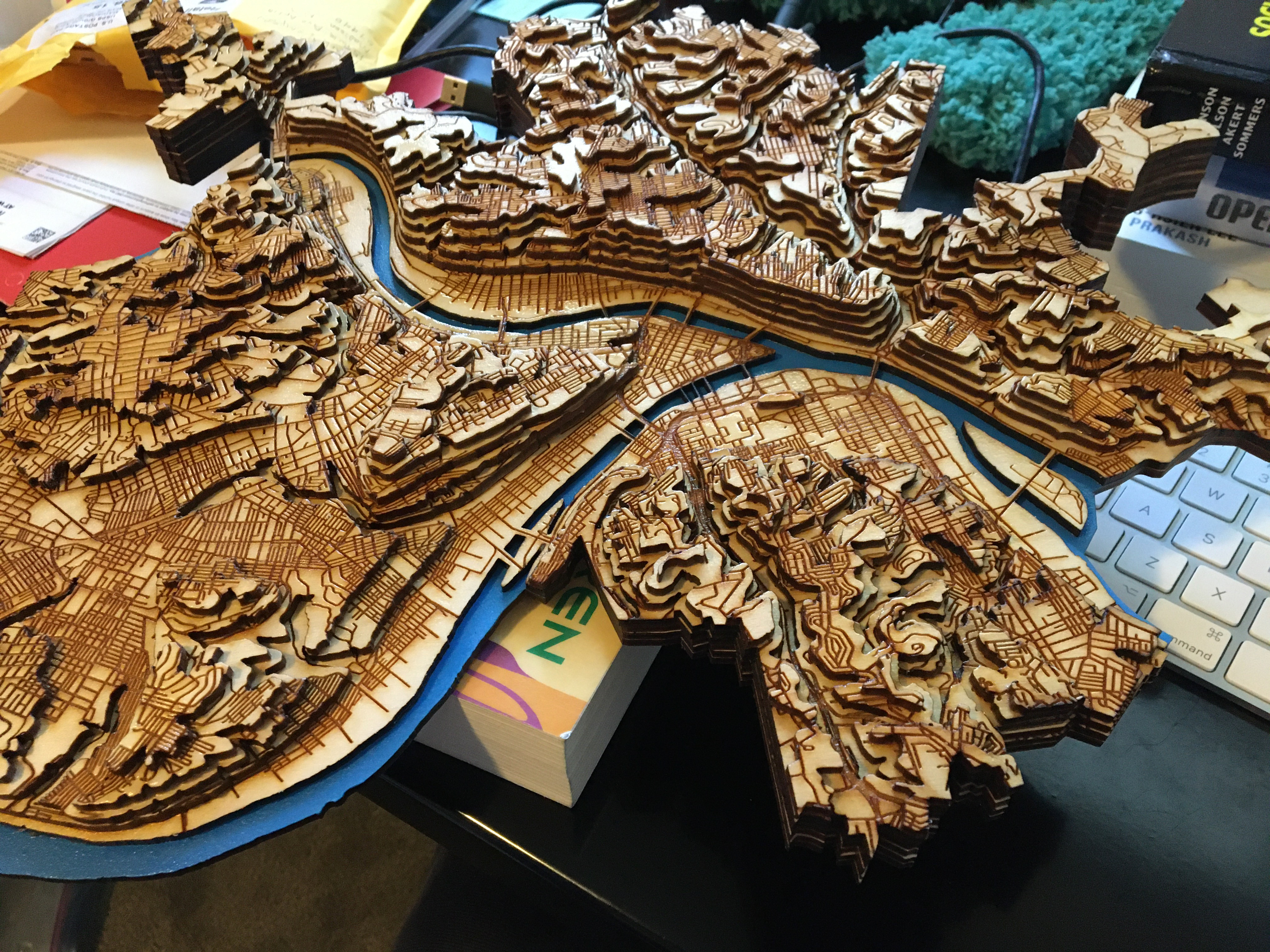
The differences in the slope of the topographic map are noticably sharper on the Mount Washington Incline.
This was a really fun project that taught me a lot about laser cutting wood and assembling multiple layers of wood into a 3D sculpture.
If I did it again, I would:
-
strongly consider using scoring / etching (blue #00FF00) the roads instead of raster engraving them to save time.
-
I’m now happy with the files I have and the edits I made, so hopefully, I wouldn’t make any errors. I made a small error on the first one I made, where the Waterworks Mall is one layer short, and the second one I made, the Waterworks Mall is one layer too tall because a clamping made the roads misalign with the layer below it, and I added a layer to correct it. The first one I made also has a “flat top” Westwood/Oakwood/East Carnegie, and the second one has more detail but I still think I missed a layer.
-
spend more time spraying sealer into the valleys, because the peaks will naturally collect overspray while the valleys won’t.